What Is PC/104?

PC/104 (IEEE P996.1) was developed to fill the need for an embedded platform, which was compliant with standardized hardware and software of the PC architecture. Mechanically quite different from the PC form factor, PC/104 modules are 3.6 X 3.8 inches in size. A self-stacking bus is implemented with pin-and-socket connectors composed of 64- and 40- contact male/female headers, which replace the card edge connectors used in standard PC hardware. Virtually anything that is available for a standard PC is available in the PC/104 form factor. PC/104 components are designed to be stacked together to create a complete embedded solution. Normally there will be a single CPU board and several peripheral boards connected by the PC/104 (ISA) system bus. Often there will be a PCI bus provided by the CPU board that will accommodate PCI peripheral boards (this standard is called PC/104+). Overall the price point for a highly integrated PC/104 CPU module is lower than for a comparable IBM-compatible PC. However, due to the power dissipation constraints typically found in embedded applications, CPU horsepower is generally lower. For more look at the PC/104 consortium site .
Power Base
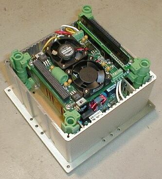
The MiniCluster power base is a custom assembly available from Parvus Corporation. Referring to the parts list, the power base is composed of a custom extrusion, end plate, power entry module, open frame power supply, and (Parvus P/N PRV-0974A-01) PC/104 power interface w/ temperature sensing. The end plate and custom extrusion form the base for the MiniCluster. The custom extrusion is machined for the power entry module and the open frame power supply. The power entry module contains a power cord receptacle, fuse, and power switch. Switched 110Vac from the power entry module is wired to the open frame power supply, which supplies all required DC voltages for the PC/104 stack. DC outputs supplied by the open frame power supply feed the PC/104 power interface module, which is the first (bottom) module in the stack. The PC/104 power interface module contains two fans, which ventilate the bottom of the stack and the open frame power supply.
For those hearty souls wishing to construct their own power base, the open frame power supply is manufactured by Connor Power Supplies (800) 235-5929 www.condorpower.com. For technical information, reference the model GLC65A switching power supply. The PC/104 power interface module specifications are listed here.
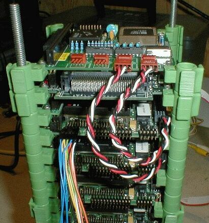
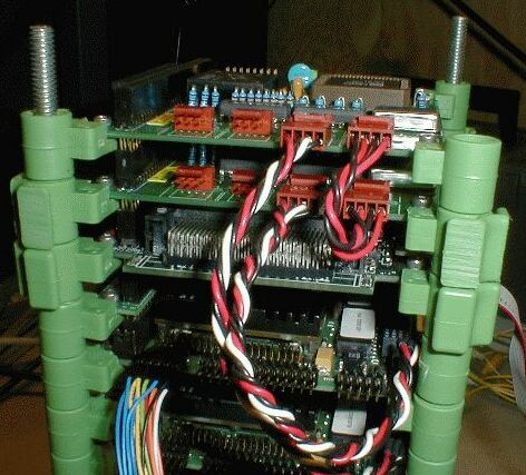
Power Bus
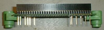
The CPU modules in the system are operated as Single Board Computers (SBCs) with the exception of the top CPU in the stack. The bottom three CPUs need only be supplied power on the PC/104 bus. To interrupt all PC/104 bus lines except for the bus power lines, double-height stack-through adapters are used to connect the CPU boards together, and all PC/104 bus connections except power connections are interrupted by means of cutting pins on the adapters.
CPU Modules
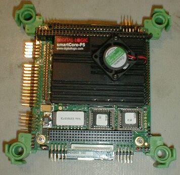
Advanced Digital Logic MSMP5SEN/SEV CPU’s are used in the MiniCluster, sporting the following features: Pentium II 266 MHz, 128 MB DRAM, LPT1 parallel port, COM1 & COM2 serial ports, speaker, PS/2 or AT keyboard interface, PS/2 mouse interface, floppy disk interface, AT-IDE hard disk interface, VGA/LCD interface, 10/100Mbit Ethernet interface, (Optional) video input with frame grabber, (optional) compact flash socket, and many more features.
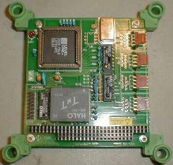
Dual PCMCIA Interface Module
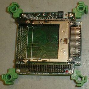
The Parvus PRV-1016X-03 PC/104 dual left loading PCMCIA interface works with PC Cards and compact flash devices. The board uses the Intel (Cirrus Logic) PD6722 chip which works well in Linux systems. This interface is used to provide a second (wired or wireless) network interface on node 1 (top CPU in the stack) of the MiniCluster. The second network interface is used to connect to the public network. Since Node 1 has both private and public network interfaces it may act as a routing or masquerading node for the cluster. All modules above Node 1 in the stack (Hubs, PCMCIA interface, and Quad CPU switch) share a full PC/104 bus with Node 1. Install the PCMCIA interface module with default Parvus configuration. Refer to the manual.
Hubs
The PRV-0752X-01 pC/104 10Mbit Ethernet hub board has four 10BaseT ports, one AUI port, and one 10Base2 (thin net) port. As configured in the MiniCluster, two of these hub cards are installed in the stack. One TP port on each hub module is used to interconnect the hubs – leaving six ports available. Four of the ports are used to connect the stack CPUs on a private network, one port is connected to an RJ-45 jack on the MiniCluster end plate (making the MiniCluster private network available to the outside world) and one port is unused (spare). Refer to the Parvus “PC/104 Ethernet Products User Manual” for configuration and connection options.
KVM Switch
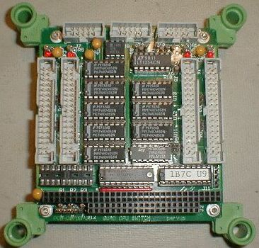
The Parvus PRV-0886X-01 Quad CPU Switch is essentially a KVM switch, which is integral to the PC/104 MiniCluster stack. This module also routes reset, speaker, and COM port lines to a specific CPU that it is switched to. The quad CPU switch has proven to be very useful in performing local and diagnostic operations on the MiniCluster. Refer to the Quad CPU Switch manual (pg.2) for the board and connector layout. When configuring this module be sure to jumper off the P1, P2, P3, P4 power select options. Leave the card in the default base address configuration. If an external CPU Selector switch is used, be sure to remove the 74HC574 chip from sock U7. Refer to the PC/104 Quad CPU Switch manual.
End Plate Wiring
PS/2 adapter for keyboard/mouse, reset switch, speaker connections are made to the Quad CPU Switch J8-utility connection. Refer to the Quad CPU Switch manual, pg.4
VGA port adapter is connected to the Quad CPU Switch J9-VGA. Refer to the Quad CPU Switch manual, pg.5. A cable is available from Parvus (CBL-1009a-01).
External CPU Select Switch is connected to Quad CPU Switch J11. Refer to pg.6, Quad CPU Switch manual
COM Port DB-9P connector can be connected to the Quad CPU Switch J7. Refer to pg.5, Quad CPU Switch manual. A cable is available from Parvus (CBL-1010a-01).
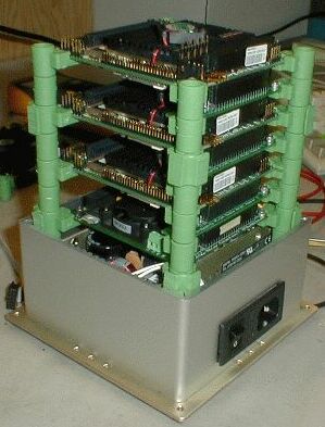
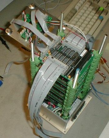
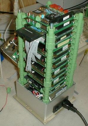
Generalized Minicluster Construction Notes
The MiniCluster is built with Parvus SnapStick components, which form an incremental card cage as modules are put into the stack. Refer to the Parvus SnapStick webpage for more information on Snapstick Components.
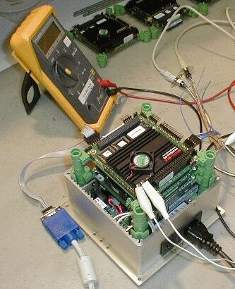
Connect a CPU Module to the Power Base via a modified double-height adapter (bus power adapter) and power the stack. Check PC/104 bus voltages. Attach Advanced Digital Logic keyboard/video/utility cable set to the CPU under test and check the CPU for proper operation. Install a compact flash microdrive with preinstalled operating system and power the stack. Check for proper operation.
Continue to add power bus adapter/CPU modules to the stack, checking each CPU for proper operation each time a new CPU is added.
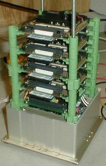
After the fourth CPU is added to the stack, add the PCMCIA adapter interface to the stack by use of a pc/104 double height adapter. Power the stack and check that to PCMCIA module detects correctly under Linux. The CPU Modules are numbered one to four, top to bottom (of the stack). The Node 1 CPU is connected to the PCMCIA interface.
Install a hub module into the stack. Test for proper private network operation by connecting two nodes to the hub, powering stack, and running ping tests against each of the nodes under test.
Install the second hub module into the stack. Cross connect the two hub modules, and connect two nodes – one to a port on each of the two hub modules, power the stack and run ping tests against each of the nodes under test. This completes the test for each of the hub modules.
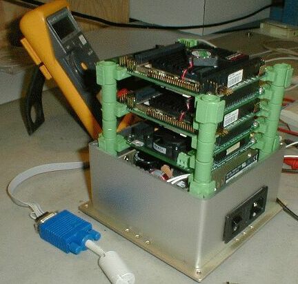
Remove the PCMCIA/HUB/HUB substack above node 1 and install the Quad CPU Switch module. Connect the end plate to the Quad CPU Switch to supply mouse/keyboard/VGA monitor connection to the Quad CPU Switch. Connect a CPU to the Quad CPU Switch (utility/com/VGA connections). Select the channel under test with the external CPU select switch. Power the stack and check for proper operation of Quad CPU Switch.
Connect remaining CPU com/utility/VGA cables to the Quad CPU Switch. Power the stack, switch between each node and check for proper operation of each CPU and of the Quad CPU Switch.
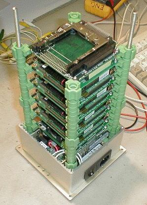
Once the Quad CPU Switch has been integrated into the stack, reinstall the PCMCIA/Hub/Hub substack into the stack. Power the stack and check for proper operation.
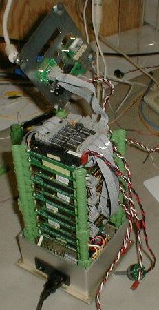
If not performed prior to this point, 1/4-20 threaded rod should be inserted into each SnapStick corner and screwed into the power base SnapMounts. The SnapStick assembly should be tightened at the top by use of a SnapWrench applied to each of the top SnapNuts. The end plate is bolted to the 6/32 nut end of the SnapNut.
Slide the MiniCluster plastic case over the top of the stack. The cover should interface well with each set of SnapGuides in the SnapStick cage. Connect the case fans to the power base 5V screw terminal just prior to pushing the case all the way to contact the powerbase extrusion.
Attach the case top plate to the stack end plate with sheet metal screws.
Happy Parallel Computing!